FreeFlyer's optimal control capabilities can be used to solve a variety of problems related to trajectory design, maneuver planning, and more. Optimization features are available in FreeFlyer's Mission tier.
The following Sample Mission Plans (included with your FreeFlyer installation) demonstrate the use of the TrajectoryPhase object:
|
The basic components of an optimization problem work flow are as follows, in order:
1.Define the problem a.Create and Initialize a TrajectoryPhase Object 2.Load the optimization engine a.Add Trajectory Phases to the Optimizer b.Define Phase Links and Add General Constraints 4.Retrieve the best solution |
At the bottom of the page is a completed example demonstrating a continuous thrust orbit change maximizing delivered fuel which uses many of the properties and methods introduced on this page.
Creating and Initializing a TrajectoryPhase Object
A TrajectoryPhase object can be created either through the object browser or via FreeFlyer script, but must be edited through script. Once the TrajectoryPhase object has been created, users have the ability to edit properties and methods that pertain specifically to the collocation dynamical solver through the TrajectoryPhase.CollocationOptions property. The example below demonstrates creating a TrajectoryPhase object and configuring the ForceModel through the TrajectoryPhase.CollocationOptions property:
// Initialize TrajectoryPhase object TrajectoryPhase phase;
phase.CollocationOptions.ForceModel.Sun = 0; phase.CollocationOptions.ForceModel.Moon = 0; phase.CollocationOptions.ForceModel.PlanetFieldType[2] = 0; phase.CollocationOptions.ForceModel.Drag = 0; |
Users may also choose to use integration for dynamical enforcement. The TrajectoryPhase.DynamicalEnforcementMethod property can be used to set the method used to enforce the equations of motion when optimizing the TrajectoryPhase. Users can edit the properties and methods that pertain specifically to integration through the TrajectoryPhase.IntegrationOptions property. Note that modifying the TrajectoryPhase.IntegrationOptions.Integrator.ForceModel property will also modify the TrajectoryPhase.CollocationOptions.ForceModel property and vice verse.The example below demonstrates how to transition from collocation to integration during the final stages of solving a trajectory optimization problem:
// Initialize TrajectoryPhase object TrajectoryPhase phase;
// Solve the problem using collocation
// Transition to integration for higher fidelity phase.DynamicalEnforcementMethod = 1; // 0: Collocation, 1: Integration
phase.Cd = 0.5; phase.DragArea = 10;
phase.IntegrationOptions.SetIntegratorType("RK45");
phase.IntegrationOptions.Integrator.FixedStep = 0; phase.IntegrationOptions.Integrator.Tolerance = 1e-6;
// Re-solve the problem |
Configure the Control Model
The TrajectoryPhase object currently supports three control models: ballistic, simple thruster, and ideal solar sail to use for analysis through the TrajectoryPhase.ControlType property. All control models and their associated variables are formulated in ICRF. The example below demonstrates configuring a TrajectoryPhase with a Simple Thruster control model:
// Choose a control model // ControlType = 0: Ballistic // ControlType = 1: Simple Thruster // ControlType = 2: Ideal Solar Sail
phase.ControlModel.ControlType = 1;
// Simple Thruster phase.ControlModel.SimpleThrusterOptions.Thrust = 5; // N phase.ControlModel.SimpleThrusterOptions.Isp = 800; // s phase.ControlModel.SimpleThrusterOptions.DutyCycle = 1; |
For more information on control models and the properties associated with the supported control models, see the Control Models guide.
Generate Initial Guess
After the TrajectroyPhase has been initialized, the next step is to define the problem that must be solved. This involves setting up a Spacecraft object and adding nodes to the TrajectoryPhase object.
Set up Spacecraft
The first step is to configure a Spacecraft object which will be used to add nodes to the TrajectoryPhase object. This process includes defining the Spacecraft's Force Model and assigning an initial state to be used for propagation. Note, the Spacecraft object and initial guess for the TrajectoryPhase can also be set up using an Ephemeris object.
// Configure the Spacecraft and its ForceModel Spacecraft sc; Alias scFM = (sc.Propagator AsType Integrator).ForceModel; scFM.Sun = 0; scFM.Moon = 0; scFM.PlanetFieldType[2] = 0; scFM.Drag = 0; sc.MassTotal = 1000; |
Adding Nodes
Nodes represent the discretized path of the TrajectoryPhase. Nodes are added to the underlying TrajectoryNodes of the TrajectoryPhase object through the TrajectoryPhase.AddNode() and TrajectoryPhase.AddNodes() methods.
TrajectoryPhase.AddNode()
Nodes can be added using the TrajectoryPhase.AddNode() method through four different overloads as shown below:
1.TrajectoryPhase.AddNode(Spacecraft spacecraft): Add a node to the TrajectoryPhase object using the current state of the passed Spacecraft.
phase.AddNode(sc); |
Note: If the Spacecraft's central body differs from the TrajectoryPhase's central body, a state conversion will take place automatically before the TrajectoryNode is added.
2.TrajectoryPhase.AddNode(TrajectoryNode trajectoryNode): Add a state to the TrajectoryPhase object using the passed TrajectoryNode.
phase1.AddNode(phase2.LastNode); |
3.TrajectoryPhase.AddNode(Spacecraft spacecraft, Array controlVariables): Add a state to the TrajectoryPhase object using the current state of the passed Spacecraft. The node control variables will also be assigned using the control Array argument.
Array controlVariables = {0.3,0.3,0.3};
phase.AddNode(sc, controlVariables); |
Note: The number and order of elements in the controlVariables Array must equal the number and order of control variables in the selected ControlModel. Refer to the TrajectoryPhase.ControlModel property for more information on control variables.
4.TrajectoryPhase.AddNode(Array posvel, Variable mass, TimeSpan epoch, Array controlVariables): Adds a state to the TrajectoryPhase using the passed position, velocity, mass, epoch, and control variables.
phase.AddNode(sc.GetCartesianState(), sc.Mass, sc.Epoch, controlVariables); |
TrajectoryPhase.AddNodes()
Nodes can be added using the TrajectoryPhase.AddNodes() method through three different overloads as shown below:
1.TrajectoryPhase.AddNodes(Ephemeris ephemeris): Uses the position, velocity, mass, and epoch data from the Ephemeris to create new TrajectoryNodes.
Ephemeris scEphem; phase.AddNodes(scEphem); |
2.TrajectoryPhase.AddNode(TrajectoryPhase trajectoryPhase): Appends TrajectoryNodes from the passed TrajectoryPhase to the calling TrajectoryPhase.
TrajectoryPhase phaseEarthToMoon; TrajectoryPhase phaseMoon;
// Append phaseMoon nodes to the phaseEarthToMoon TrajectoryPhase phaseEarthToMoon.AddNodes(phaseMoon); |
3.TrajectoryPhase.AddNode(Spacecraft spacecraft, TimeSpan duration, Variable numberOfNodes, Variable resetSpacecraftState): Propagates the passed Spacecraft using its current Propagator for the passed duration and saves numberOfNodes equally spaced TrajectoryNodes during the propagation. If resetSpacecraftState = 1, then the Spacecraft's state will be restored to its original state once the process is complete.
// Propagate the Spacecraft for 3 days creating 5 equally spaced nodes phase.AddNodes(sc, TimeSpan.FromDays(3), 5, 0); |
Resampling Nodes
The TrajectoryPhase.ResampleNodes() method re-interpolates the TrajectoryPhase's nodes using new node spacing. Although you cannot change discretization while solving the problem, a common approach is to solve the problem using a relatively sparse discretization so it is easy for the optimizer to solve the problem, then resample to have a higher number of nodes. The script below demonstrates setting up a TrajectoryPhase object which is added to a ViewWindow for visualization. After setting up the TrajectoryPhase object, adding nodes to the TrajectoryPhase, and adding the TrajectoryPhase to the Optimizer, users can add any of the ResampleNodes() method calls to the bottom of the script to gain a better understanding of how nodes are resampled.
// Initial Setup Spacecraft sc; sc.A = 20000; sc.E = 0.4; sc.I = 0.001; sc.TA = 0.001;
TrajectoryPhase phase;
// Draw nodes in the ViewWindow phase.DrawNode = 1;
// Add nodes to the TrajectoryPhase phase.AddNodes(sc, TimeSpan.FromMinutes(sc.Period*0.5), 100, 0);
ViewWindow vw; vw.AddObject(phase);
Optimizer opt; opt.AddTrajectoryPhase(phase); |
Nodes can be resampled using the TrajectoryPhase.ResampleNodes() method through three different overloads as shown below:
1.TrajectoryPhase.ResampleNodes(Variable numberOfPoints): Re-interpolates the TrajectoryPhase's nodes using a uniform spacing of node points in time.
phase.ResampleNodes(30); |
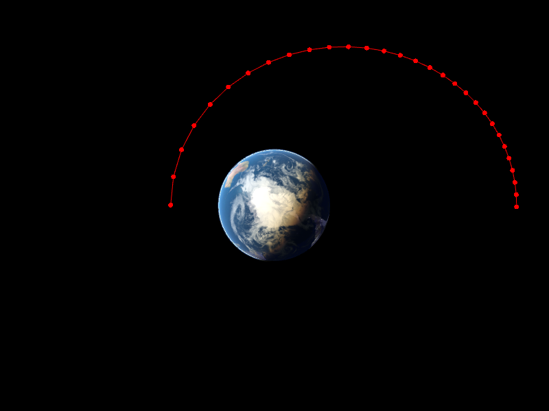
Uniform Overload
2.TrajectoryPhase.ResampleNodes(Array numberOfPointsArray, Array barriers): Re-interpolates the TrajectoryPhase's nodes using independent uniform distributions of TrajectoryNodes in time within user-defined barriers.
// Resample such that there are 20 nodes in the first 30% of the trajectory and 10 nodes in the last 70% of the trajectory phase.ResampleNodes({20, 10}, {0, 0.3, 1}); |
Note: The numberOfPoints Array must have one less element than the barriers Array argument. Additionally, the barriers Array argument must begin with 0 and end with 1.
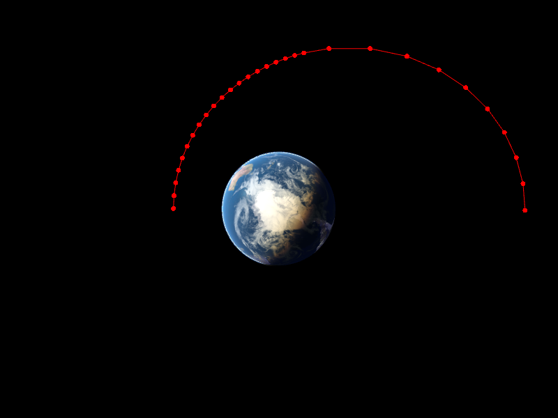
First 30%: 20 nodes
Last 70%: 10 nodes
3.TrajectoryPhase.ResampleNodes(Variable numberOfPoints, String shape, Variable weight):
// Resample nodes such that there are 30 nodes concentrated at the start of the trajectory phase.ResampleNodes(30, "start", 4); |
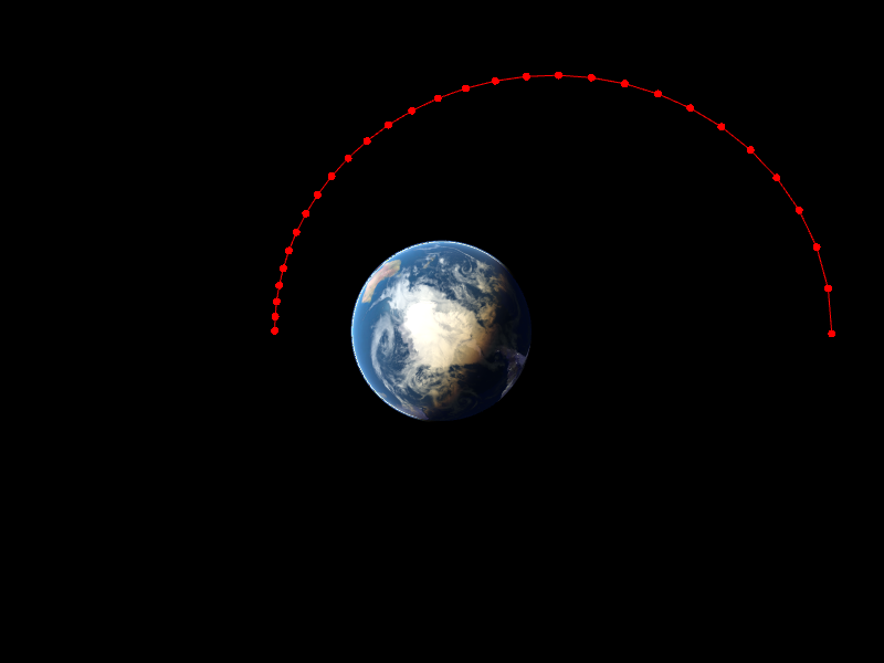
"Start" Overload
// Resample nodes such that there are 30 nodes concentrated at locations in the trajectory that are closest to the central body // The weight of 4 results in a higher node concentration in the locations where Spacecraft is closest to the central body. phase.ResampleNodes(30, "radius", 4); |
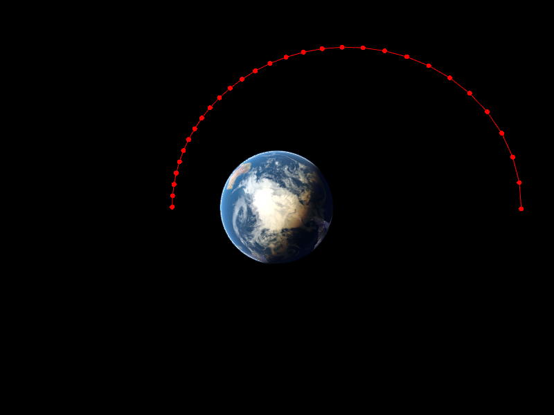
"Radius" Overload
// Resample nodes such that there are 30 nodes concentrated at locations in the trajectory where acceleration is greatest // The weight of 4 results in a higher node concentration in the locations where acceleration is greater. phase.ResampleNodes(30, "acceleration", 4); |
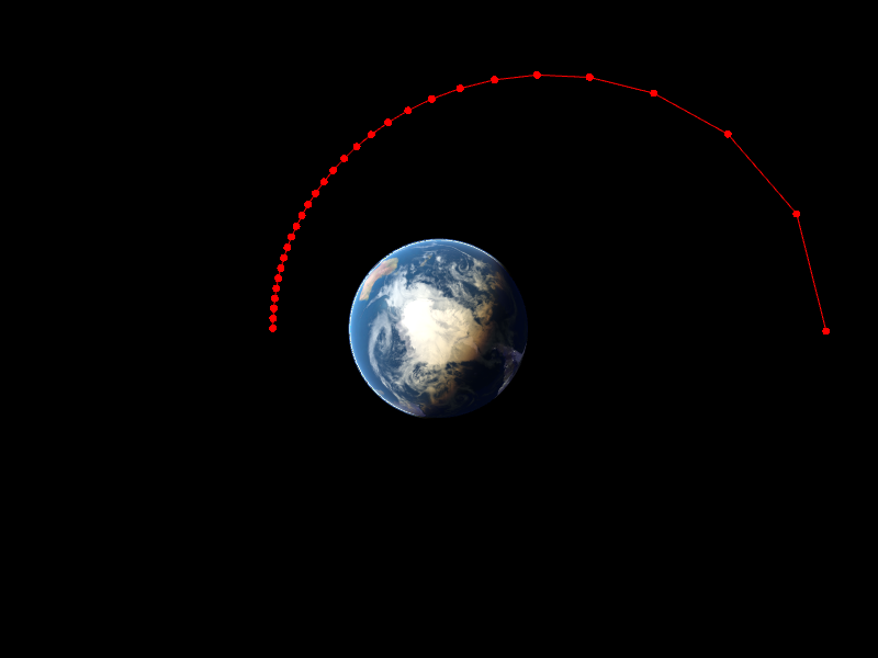
"Acceleration" Overload
Example: Adding Nodes to a TrajectoryPhase
The script example below demonstrates configuring a Spacecraft with a semi-major axis of 10,000 km and propagating it for one period adding one node to the TrajectoryPhase object at each step. Once all the nodes have been added to the TrajectoryPhase, the TrajectoryPhase.ResampleNodes() method is called to re-interpolate the TrajectoryPhase's nodes creating 50 uniform spaced node points.
// Initialize TrajectoryPhase object TrajectoryPhase phase;
phase.CollocationOptions.ForceModel.Sun = 0; phase.CollocationOptions.ForceModel.Moon = 0; phase.CollocationOptions.ForceModel.PlanetFieldType[2] = 0; phase.CollocationOptions.ForceModel.Drag = 0;
// Configure the TrajectoryPhase to have a 'Simple Thruster' control model and set thruster parameters phase.ControlModel.ControlType = 1; phase.ControlModel.SimpleThrusterOptions.Thrust = 100; phase.ControlModel.SimpleThrusterOptions.Isp = 200;
// Configure the Spacecraft and its ForceModel Spacecraft sc; Alias scFM = (sc.Propagator AsType Integrator).ForceModel; scFM.Sun = 0; scFM.Moon = 0; scFM.PlanetFieldType[2] = 0; scFM.Drag = 0; sc.MassTotal = 1000;
sc.A = 10000; sc.E = 0.0001; sc.I = 10; sc.TA = 0;
// Create TimeSpan object for propagation loop TimeSpan stepTo = sc.Epoch + (sc.Period).ToTimeSpan("min");
// Propagate the Spacecraft for 1 period, adding a node at each Step WhileStepping sc to (sc.Epoch == stepTo); phase.AddNode(sc); End;
// Report the number of nodes in the TrajectoryPhase before re-sampling nodes Report phase.Nodes.Count;
// Re-interpolate the TrajectoryPhase's nodes to create 50 uniform spaced node points phase.ResampleNodes(50);
// Report the number of nodes in the TrajectoryPhase after re-sampling nodes Report phase.Nodes.Count; |
Set Bounds
To further constrain the problem, users can set bounds on variables associated with the TrajectoryPhase through a number of useful methods. These variables can be locked at the "first" or "last" node of the TrajectoryPhase or along the entire "path" of the TrajectoryPhase with a passed range and/or index.
1.SetPositionBounds(): Set bounds for the Cartesian position variables associated with the passed range and index.
// Set bounds for all Cartesian position variables at the first node of the TrajectoryPhase // Lower Bound: -5000 km, Upper Bound: 5000 km phase.SetPositionBounds("first", -5000, 5000);
// Set bounds for the X Cartesian position variable along the entire path of the TrajectoryPhase // Lower Bound: -5000 km, Upper Bound: 5000 km phase.SetPositionBounds("path", -5000, 5000, 0); |
Note: An index of 0 indicates the first (X) position variable.
2.SetVelocityBounds(): Set bounds for the Cartesian velocity variables associated with the passed range and index.
// Set bounds for all Cartesian velocity variables at the first node of the TrajectoryPhase // Lower Bound: -1 km/s, Upper Bound: 1 km/s phase.SetVelocityBounds("last", -1, 1);
// Set bounds for the VZ Cartesian velocity variable along the entire path of the TrajectoryPhase // Lower Bound: -1 km/s, Upper Bound: 1 km/s phase.SetVelocityBounds("path", -1, 1, 2); |
Note: An index of 0 indicates the first (VX) position variable.
3.SetMassBounds(): Set bounds for the TrajectoryPhase mass associated with the passed range.
// Lower Bound: 0 kg, Upper Bound: 1e3 kg phase.SetMassBounds("last", 0, 1e3); |
4.SetEpochBounds(): Set bounds for the TrajectoryPhase epoch associated with the passed range.
// Lower Bound: 0 days, Upper Bound: 3 days phase.SetEpochBounds("first", TimeSpan.FromDays(0), TimeSpan.FromDays(3)); |
5.SetTimeOfFlightBounds(): Set bounds for the time of flight of the TrajectoryPhase.
// Constrain time of flight to 1.5 - 2.5 days for the TrajectoryPhase phase.SetTimeOfFlightBounds(TimeSpan.FromDays(1.5), TimeSpan.FromDays(2.5)); |
6.SetControlVariableBounds(): Set bounds for the TrajectoryPhase's control variables associated with the passed range and indices.
// Set bounds for the first 3 control variables at the first node of the TrajectoryPhase // Lower Bound: 0, Upper Bound: 1, Index: 0-2 phase.SetControlVariableBounds("first", {0,0,0}, {1,1,1}, {0,1,2});
// Set bounds for the first control variable along the path the TrajectoryPhase // Lower Bound: 0, Upper Bound: 0.5, Index: 0 phase.SetControlVariableBounds("path", 0, 0.5, 0); |
Note: An index of 0 indicates the first control variable.
Lock Variables
The TrajectoryPhase object allows users to 'Lock' variables through a number of useful methods. These variables can be locked at either the "first" or "last" node in the TrajectoryPhase and/or can be passed user-defined values for either endpoint.
1.LockPosition(): Lock Cartesian position variables associated with the passed endpoint to their current values or to user defined passed values.
// Lock Cartesian position variables at the first node of the TrajectoryPhase phase.LockPosition("first");
// Lock Cartesian position variables at the first node of the TrajectoryPhase using the values from the first node phase.LockPosition("first" , phase.FirstNode.Position); |
2.LockVelocity(): Lock Cartesian velocity variables associated with the passed endpoint to their current values or to user defined passed values.
// Lock Cartesian velocity variables at the last node of the TrajectoryPhase phase.LockVelocity("last");
// Lock Cartesian velocity variables at the last node of the TrajectoryPhase at the passed user-defined values phase.LockVelocity("last" , {1.5, 0, 0}); |
3.LockPositionVelocity(): Lock Cartesian position and velocity variables associated with the passed endpoint to their current values or to user defined passed values.
// Lock Cartesian position and velocity variables at the last node of the TrajectoryPhase phase.LockPositionVelocity("last");
// Lock Cartesian position variables at the last node of the TrajectoryPhase and velocity variables at the passed user-defined values phase.LockPositionVelocity("last" , {phase.LastNode.Position, {1.5, 0, 0}}); |
4.LockMass(): Lock the TrajectoryPhase mass variable associated with the passed endpoint to their current values or to user defined passed values.
// Lock mass variable at the last node of the TrajectoryPhase phase.LockMass("last");
// Lock mass variable at the last node of the TrajectoryPhase to 1500 kg phase.LockMass("last" , 1500); |
5.LockEpoch(): Lock the TrajectoryPhase epoch variable associated with the passed endpoint to their current values or to user defined passed values.
// Lock epoch variable at the first node of the TrajectoryPhase phase.LockEpoch("first");
// Lock mass variable at the first node of the TrajectoryPhase using the values from the first node phase.LockEpoch("first" , phase.FirstNode.Epoch); |
6.Lock(): Locks all TrajectoryPhase position, velocity, mass, and epoch variables associated with the passed endpoint argument to their current values.
phase.Lock("first"); phase.Lock("last"); |
7.LockByIndices(): Locks only the TrajectoryPhase variables associated with the passed endpoint and indices.
// Indices // 0: X Cartesian Position, 1: Y Cartesian Position, 2: Z Cartesian Position // 3: X Cartesian Velocity, 4: Y Cartesian Velocity, 5: Z Cartesian Velocity // 6: Mass, 7: Epoch
// Lock X,Y,Z Position and Z velocity at the first node phase.LockByIndices("first", {0,1,2,5});
// Lock X,Y,Z Velocity and Mass at the last node phase.LockByIndices("last", {3,4,5,6});
// Lock all variables at the last node (Equivalent to Lock("last")) phase.LockByIndices("last", {1,2,3,4,5,6,7}); |
Note: Any indices after 7 represent potential control variables. Certain control variable indices may or may not exist depending on which ControlModel is selected.
8.LockTimeOfFlight(): Locks the time of flight of the TrajectoryPhase to the current value or to a user defined passed value.
// Lock time of flight to current value phase.LockTimeOfFlight();
// Lock time of flight to 10 days phase.LockTimeOfFlight(TimeSpan.FromDays(10)); |
9.LockControlVariables(): Locks the TrajectoryPhase control variables associated with the passed endpoint and index to its current or user defined passed values.
// Lock control variables for the first node of the TrajectoryPhase phase.LockControlVariables("first");
// Lock second control variable for the first node of the TrajectoryPhase phase.LockControlVariables("first", 1);
// Lock first control variable for the first node of the TrajectoryPhase to 0.3 phase.LockControlVariables("first", 0, 0.3); |
Note: An index of 0 indicates the first control variable.
Example: Initial Configuration for an Earth to Mars Low-Thrust transfer
The script example below demonstrates configuring a Spacecraft performing a low thrust transfer from Earth to Mars. Two TrajectoryPhases are configured, one for the Earth outbound leg and one for the Mars inbound leg of the trajectory. Both TrajectoryPhases are configured with a 'Simple Thruster' control model. The Earth outbound leg of the trajectory (phaseEarth) is loaded with node points by forward propagating to the epoch at the "midpoint" of the initial guess trajectory, then the ResampleNodes() method is called to create 25 uniform nodes along the path. The Mars inbound leg of the trajectory (phaseMars) is loaded with node points by backwards propagating from the end epoch to the epoch at the "midpoint" of the initial guess trajectory, then the Reverse() method is called to put the node points in order before resampling to create 25 uniform nodes along the path. The LockMass() method is called to lock the mass at the end point of the trajectory to 1287 kg, and the SetVelocityBounds() method is called to constrain both TrajectoryPhases Cartesian velocity between -100 and 100 km/s. The FirstNode.Mass property is used to minimize mass at the start of the trajectory, which is the equivalent of minimizing fuel usage.
// Initialize Earth Outbound Trajectory Segment TrajectoryPhase phaseEarth; phaseEarth.SetCentralBody(Sun); Alias phaseEarthFM = phaseEarth.CollocationOptions.ForceModel; phaseEarthFM.Earth = 0; phaseEarthFM.Moon = 0; phaseEarthFM.Drag = 0;
// Configure the TrajectoryPhase to have a 'Simple Thruster' control model and set thruster parameters phaseEarth.ControlModel.SimpleThrusterOptions.Thrust = 0.7; phaseEarth.ControlModel.SimpleThrusterOptions.Isp = 3800; phaseEarth.ControlModel.ControlType = 1;
// Initialize Mars Inbound Trajectory Segment TrajectoryPhase phaseMars; phaseMars.SetCentralBody(Sun); Alias phaseMarsFM = phaseMars.CollocationOptions.ForceModel; phaseMarsFM.Earth = 0; phaseMarsFM.Moon = 0; phaseMarsFM.Drag = 0;
// Configure the TrajectoryPhase to have a 'Simple Thruster' control model and assign thruster parameters phaseMars.ControlModel.SimpleThrusterOptions.Thrust = phaseEarth.ControlModel.SimpleThrusterOptions.Thrust; phaseMars.ControlModel.SimpleThrusterOptions.Isp = phaseEarth.ControlModel.SimpleThrusterOptions.Isp; phaseMars.ControlModel.ControlType = phaseEarth.ControlModel.ControlType;
// Configure the Spacecraft and its ForceModel Spacecraft sc; sc.SetCentralBody(Sun); Alias scFM = (sc.Propagator AsType Integrator).ForceModel; scFM.Earth = 0; scFM.Moon = 0; scFM.Drag = 0; sc.MassTotal = 1500;
// Initial Guesses for launch epoch, time of flight, and epoch at the midpoint TimeSpan launch_initialGuess = TimeSpan.FromDays(54700); TimeSpan tof_initialGuess = TimeSpan.FromDays(300); TimeSpan midpoint_initialGuess = launch_initialGuess + tof_initialGuess.Scaled(0.5);
sc.Epoch = launch_initialGuess; sc.SetCartesianState(Earth.GetPosVelAtEpoch(sc.Epoch));
// While stepping to the epoch at the midpoint add a node for each step of the Spacecraft WhileStepping sc to (sc.Epoch == midpoint_initialGuess); phaseEarth.AddNode(sc); End;
// Re-interpolate the TrajectoryPhase's nodes to create 25 uniform spaced node points phaseEarth.ResampleNodes(25);
// Reset the Spacecraft's epoch to the end point (Mars) sc.Epoch = launch_initialGuess + tof_initialGuess; sc.SetCartesianState(Mars.GetPosVelAtEpoch(sc.Epoch));
// While stepping backwards to the epoch at the midpoint add a node for each step of the Spacecraft WhileStepping sc to (sc.Epoch == midpoint_initialGuess); phaseMars.AddNode(sc); End;
// Reverse the order of the TrajectoryPhase's nodes so all nodes are in order phaseMars.Reverse();
// Re-interpolate the TrajectoryPhase's nodes to create 25 uniform spaced node points phaseMars.ResampleNodes(25);
// Lock the epoch at the first node phaseEarth.LockEpoch("first");
// Lock the mass at the last node point to be 1287 kg phaseMars.LockMass("last", 1287);
// Set velocity bounds along the entire trajectory path between -100/100 km/s for both TrajectoryPhases phaseEarth.SetVelocityBounds("path", -100, 100); phaseMars.SetVelocityBounds("path", -100, 100); |
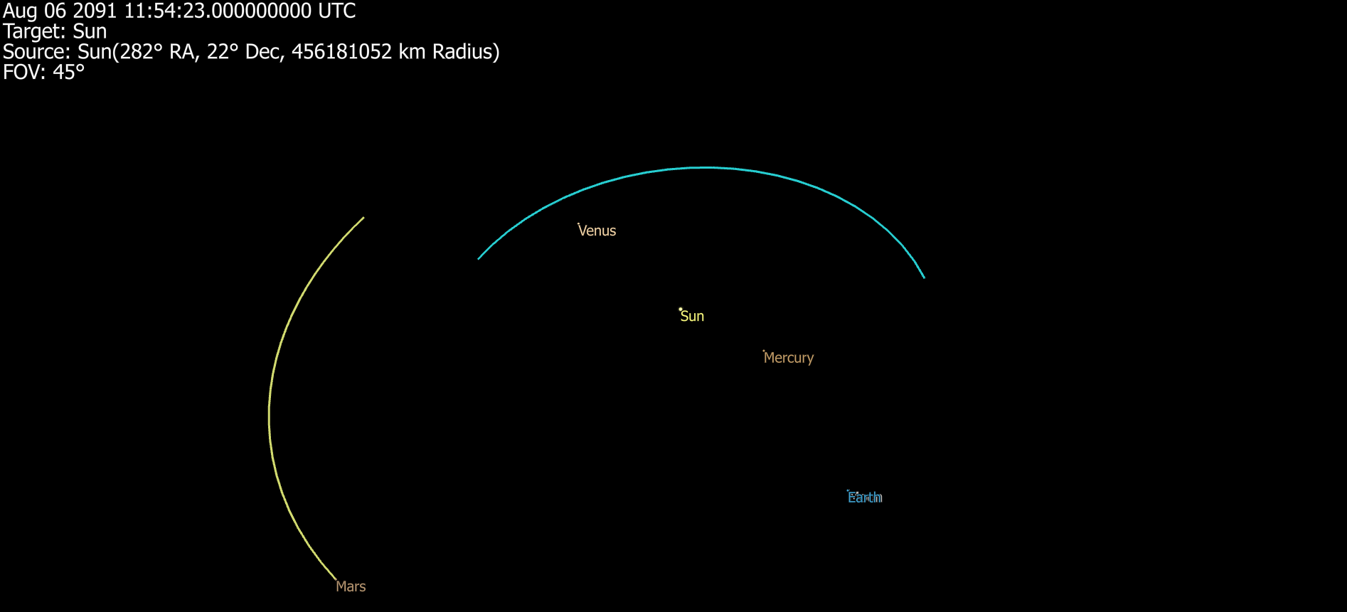
Earth to Mars Initial Guess
Blue: phaseEarth Yellow: phaseMars
Add Trajectory Phases to the Optimizer
After all TrajectoryPhases have been configured, the next step is to add the TrajectoryPhase object to the optimization problem by using the Optimizer.AddTrajectoryPhase() method. When the Optimizer.LoadEngine() method is called, all variables and constraints associated with the added TrajectoryPhases will automatically be added to the optimization problem. Continuing the example above, Initial Configuration for an Earth to Mars Low-Thrust transfer, the script example below demonstrates adding multiple TrajectoryPhase objects to the Optimizer.
// Initialize Optimizer Optimizer opt;
// Add TrajectoryPhases to the Optimizer opt.AddTrajectoryPhase(phaseEarth); opt.AddTrajectoryPhase(phaseMars); |
Users can also use the Optimizer.AddTrajectoryPhases() method to add a list of TrajectoryPhase objects to the optimizer, which is demonstrated in the script example below. For more information on configuring and using the Optimizer object, see the Using the Optimizer guide.
// Initialize list of TrajectoryPhase objects List<TrajectoryPhase> phaseList[3];
// Add list of TrajectoryPhases to the Optimizer opt.AddTrajectoryPhases(phaseList); |
Define Phase Links and Add General Constraints
Constraints are used in an optimization process to define conditions which must be met in order for a solution produced by the Optimizer object to be considered feasible. Similar to state variables, constraints can be added to the process via the Optimizer.AddConstraint() or Optimizer.AddConstraintBlock() methods, which require the user to set a label to be used to identify the constraint within the process. For more information on configuring constraints, see the Configuring Constraints section of the Using the Optimizer Guide.
When solving an optimization problem that includes multiple TrajectoryPhase objects that are intended to be continuous (e.g., Initial Configuration for an Earth to Mars Low-Thrust transfer), users have the ability to link the phases across the position, velocity, mass, and epoch variables through the Optimizer.AddPhaseLink() method. Continuing the example above, the script below demonstrates linking the last node of the phaseEarth TrajectoryPhase to the first node of the phaseMars TrajectoryPhase using two different method overloads. Both methods add constraint(s) to the optimization problem to ensure that the phases are continuous. This script example also demonstrates adding generalized constraints to the optimization problem.
// Link the last node of phaseEarth with the first node of phaseMars // Overload 1: opt.AddPhaseLink(phaseEarth, phaseMars);
// Overload 2 opt.AddPhaseLink(phaseEarth, phaseMars, "last", "first");
// Constraint Blocks: initial position/velocity, final position/velocity opt.AddConstraintBlock(3, "r0_", 0, 0, 1e6); opt.AddConstraintBlock(3, "v0_", 0, 0, 1); opt.AddConstraintBlock(3, "rf_", 0, 0, 1e6); opt.AddConstraintBlock(3, "vf_", 0, 0, 1);
// Time of flight spacer constraint opt.AddConstraint("tofSpacer", 0, 0, 1); |
Solve and Query Results
Once defined, the problem must be loaded into a third-party optimization library. FreeFlyer includes built-in support for Ipopt and NLopt. FreeFlyer also supports SNOPT, but the user must have an SNOPT license and provide the path to the SNOPT shared library file (.dll on Windows, .so on Linux). For more information on each third-party tool, see Optimization Engines.
Load the Optimization Engine
The optimization engine is loaded by calling the LoadEngine() method on the Optimizer object. If called with no arguments, Ipopt will be loaded by default.
opt.LoadEngine(); // Ipopt
opt.LoadEngine(0); // 0 = Ipopt, 1 = SNOPT, 2 = NLopt |
If using SNOPT, the user must provide the path to their shared library file. The user can specify the shared library file for Ipopt or NLopt as well, if they wish to use their own version of the library instead of the one built in to FreeFlyer.
opt.LoadEngine(1 /* SNOPT */, "mypath/snopt7.dll"); |
Each optimization engine has additional settings specific to each library. The process for accessing these tuning parameters is described on the Optimization Engines page.
Create the Evaluation Loop and Retrieve the Best Solution
The process of creating an evaluation loop and retrieving the best solution is summarized below but can be found in more detail on the Using the Optimizer guide. The basic steps of creating the evaluation loop and retrieving the best solution are as follows, in order:
1.Loop Condition: The optimization process happens within a While loop; the Optimizer object will continue to iterate until the condition in the loop evaluates to false. Two methods on the Optimizer object can be used as the loop condition, depending on the desired behavior: HasNotConverged() or IsRunning(). 2.Restore Saved Objects: The first step within the evaluation loop is to restore any objects that have been saved to the process and need to be returned to their initial state for each iteration. 3.Update and Retrieve State Variables: At the beginning of each iteration of the evaluation loop, the state variables must be updated using the Optimizer.UpdateStateVariables() method. This method advances all the state variables in the process to the Optimizer object's next guess. 4.Perform Analysis: Once the latest state variable values have been retrieved from the Optimizer object, any analysis that is necessary to calculate the constraints or objective function should be performed. This could include Spacecraft propagation, contact analysis, performing maneuvers, and more. 5.Update Constraints: Once any necessary analysis has been performed, the resulting constraints must be calculated and fed back into the Optimizer object using the Optimizer.SetConstraintValue() method. 6.Provide Known Derivatives: If desired, the user can provide the optimization engine with any known derivatives of the problem constraints or objective function by populating the Jacobian Matrix and Gradient Array properties of the Optimizer object on every nominal case iteration within the evaluation loop. This is an optional input that can improve performance; see Specifying Known Derivatives for more information. 7.Minimize or Maximize the Objective Function: The objective function defines the quantity which needs to be minimized or maximized by the Optimizer object in order to produce an optimal solution. The objective function is passed in as an argument to the Optimizer.Minimize() or Optimizer.Maximize() method, and the Optimizer object works to vary the state variable values in order to find the best solution to the objective function that meets the problem's defined constraints. 8.Solve Constraints: An alternative to minimizing or maximizing an objective function is the Optimizer.SolveConstraints() method, which finds a feasible solution to satisfy the problem constraints without needing to specify an objective function. This approach will allow the Optimizer object to converge on a solution that is feasible, but not necessarily optimal. 9.Generate Output: Data reports and graphical output can be generated within the evaluation loop of an optimization process as well as after converging on a solution and/or exiting the loop. Views, Plots, and Reporting mechanisms all behave the same way within an optimization loop as they do in any other context; FreeFlyer's suite of Optimization Sample Mission Plans contain numerous examples of output generation within an optimization process. There are various convenient properties and methods on the Optimizer object that enable the user to easily retrieve information about the optimization process both during and after iteration. Reports about the optimization process within an evaluation loop should always be generated after the call to Optimizer.Minimize(), Optimizer.Maximize(), or Optimizer.SolveConstraints() to ensure that the most up-to-date values are being reported. |
Visualization
The TrajectoryPhase object allows users to visualize nodes and paths in 3D views. The TrajectoryPhase.DrawNode property determines whether a tick mark will be drawn at the current node. The size of the drawn node can be increased or decreased using the TrajectoryPhase.NodeTickWidth property. The shape of the drawn node can be set using the TrajectoryPhase.NodeTickType property. Nodes can be colored in three different ways using the TrajectoryPhase.NodeColorMode property:
1.Constant Color
2.Collocation Defect Error - color coded according to the collocation defect error (gradient of red/orange/yellow/green). Red indicates collocation defect error, and green indicates collocation defect integrity.
3.Dynamical Error - color coded according to the dynamical error (gradient of red/orange/yellow/green). Red indicates collocation defect error, and green indicates collocation defect integrity.
// Initialize TrajectoryPhase object TrajectoryPhase phase;
phase.DrawNode = 1; // Draw nodes phase.NodeTickType = "Circle"; phase.NodeTickWidth = 10; // Increase tick mark to size 10 phase.NodeColorMode = 1; // Color based on collocation defect error |
The TrajectoryPhase.DrawPath property determines whether a line will be drawn between the previous node and the current node when updating the view. Paths can be colored in three different ways similar to coloring nodes using the TrajectoryPhase.PathColorMode property:
1. Constant Color
2. Collocation Defect Error - color coded according to the collocation defect error (gradient of red/orange/yellow/green). Red indicates collocation defect error, and green indicates collocation defect integrity.
3. Dynamical Error - color coded according to the dynamical error (gradient of red/orange/yellow/green). Red indicates collocation defect error, and green indicates collocation defect integrity.
// Initialize TrajectoryPhase object TrajectoryPhase phase;
phase.DrawPath = 1; // Draw nodes phase.PathColorMode = 2; // Color based on dynamical error |
To gain more insight into the optimization process, users have the ability to draw control vectors for a TrajectoryPhase using the TrajectoryPhase.DrawControlVector property. The TrajectoryPhase.DrawControlVector determines whether a control vector will be drawn at the current node. Note, when using a ballistic control model the control vector does not exist in which case this property has no effect. Control vectors can be colored in three different ways similar to coloring nodes using the TrajectoryPhase.ControlVectorColorMode property:
1. Constant Color
2. Collocation Defect Error - color coded according to the collocation defect error (gradient of red/orange/yellow/green). Red indicates collocation defect error, and green indicates collocation defect integrity.
3. Dynamical Error - color coded according to the dynamical error (gradient of red/orange/yellow/green). Red indicates collocation defect error, and green indicates collocation defect integrity.
The TrajectoryPhase.ControlVectorMaximumLength property determines the maximum length in kilometers of the control vectors in the mission view. When the control model is producing less than the maximum possible thrust, the actual length of the visualized control vector will be scaled down proportionately to the ratio of actual thrust to maximum possible thrust. Users can set this property to zero to have FreeFlyer scale the control vectors so that the maximum control vector length is about 1/8th the scale of the TrajectoryPhase itself in a central body-centric inertial frame.
// Initialize TrajectoryPhase object TrajectoryPhase phase;
phase.DrawControlVector = 1; // Draw control vectors phase.ControlVectorColorMode = 0; // Constant color
phase.ControlVectorMaximumLength = 100000; // 100,000 km
// FreeFlyer scale the control vectors so that the maximum control vector length is // about 1/8th the scale of the TrajectoryPhase itself in a central body-centric inertial frame phase.ControlVectorMaximumLength = 0; |
Complete Example
The Continuous Thrust Orbit Change example that has been constructed throughout this page is presented in its entirety below, with descriptions to indicate each section of the workflow.
![]() Continuous Thrust Orbit Change
Continuous Thrust Orbit Change
|
Output
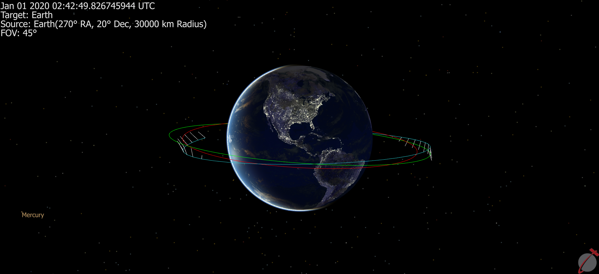
Continuous Thrust Example: ViewWindow
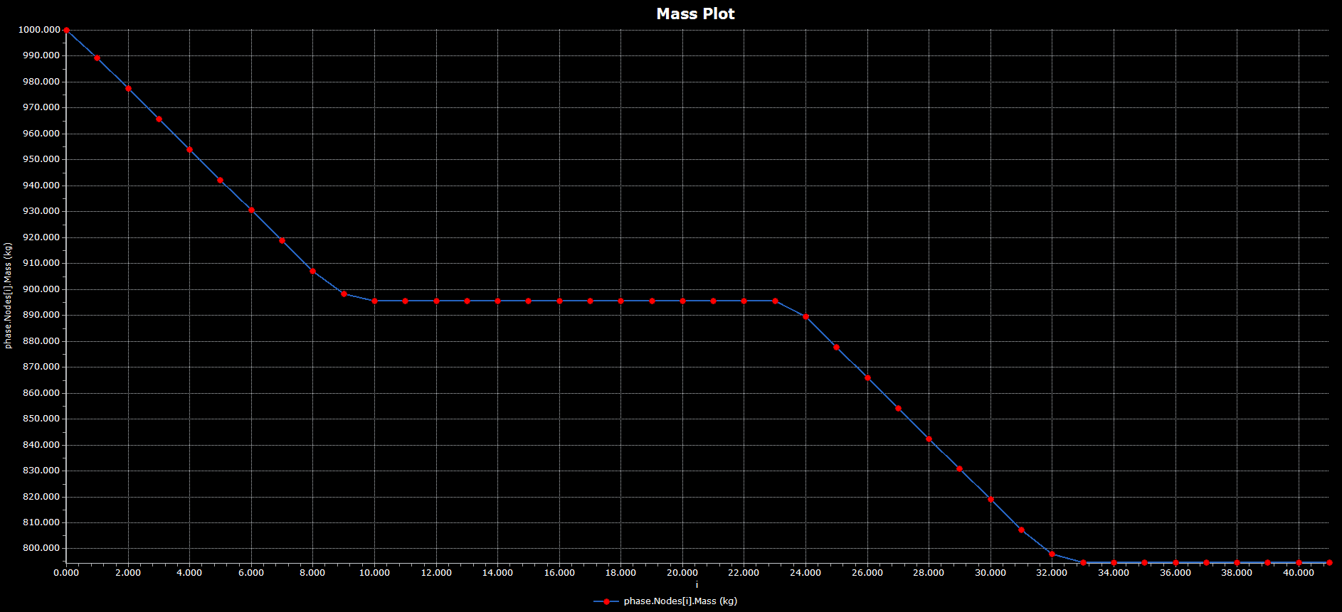
Continuous Thrust Example: Mass Plot
This page contains all of the basic components needed to configure a TrajectorySegment object for use within an optimization problem. For more information on the collocation algorithm or control models please see the respective page in the Optimal Control Guide.
See Also
•Trajectory Phases Guide •TrajectoryPhase Object •TrajectoryNode Object |