The attitude reference frame defines the coordinate system to which the Spacecraft's attitude is referenced. The AttitudeConvert function and RelativeMotionUtilities object can be used to convert attitudes between any of the supported systems, which are as follows. To find information about the non-attitude orbital reference frames available in FreeFlyer, that can be found in the Orbit Reference Frames guide.
Cartesian Frames
The following frames are Cartesian reference frames used for defining a Spacecraft's attitude.
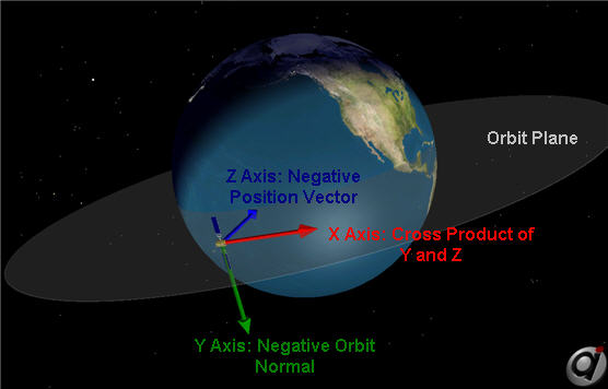
LVLH
Description:
•Z-axis: Vector pointing in the opposite direction to the position vector (points to center of Spacecraft's Central Body) •Y-axis: Vector pointing in the opposite direction to the orbit normal (the orbit normal is the cross product of position and velocity) •X-axis: Vector perpendicular to the y- and z-axes, forming a right-handed coordinate system •Origin: Center of the Spacecraft |
Prior to setting the Spacecraft's attitude state, its attitude reference frame must be set:
Spacecraft1.AttitudeRefFrame = "LVLH";
// or
Spacecraft1.SetAttitudeRefFrame(0); |
The EulerAnglesLVLH property can be used to display the Euler Angles that define the orientation of the Spacecraft BCS with respect to the LVLH frame:
Report Spacecraft1.EulerAnglesLVLH; |
International Celestial Reference System (ICRF)
Description:
•Axes: The directions of the axes are fixed with respect to a set of extragalactic objects. The celestial reference system is constructed such that its principal plane is as close as possible to the Mean of J2000 Earth Equator and that the origin of the principal plane should be as close as possible to the dynamical equinox of J2000. •Origin: Spacecraft's Central Body |
Prior to setting the Spacecraft's attitude state, its attitude reference frame must be set:
Spacecraft1.AttitudeRefFrame = "ICRF";
// or
Spacecraft1.SetAttitudeRefFrame(1); |
The EulerAnglesICRF property can be used to display the Euler Angles that define the orientation of the Spacecraft BCS with respect to the ICRF frame:
Report Spacecraft1.EulerAnglesICRF; |
Notes:
|
•Inertial frame. •This is the principal coordinate system used for computations in FreeFlyer. |
References:
1."IERS Conventions 2010," Luzum, B., & Petit, G., IERS Technical Note No. 36 (2010) |
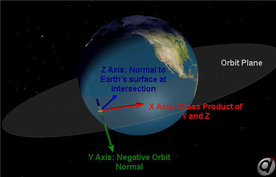
Geodetic
Description:
•Z-axis: Vector pointing toward Earth which is normal to the Earth's surface at intersection with Earth's surface •Y-axis: Vector pointing the opposite direction of the orbit normal •X-axis: Vector perpendicular to the y- and z- axes, forming a right-handed coordinate system •Origin: Center of the Spacecraft |
Prior to setting the Spacecraft's attitude state, its attitude reference frame must be set:
Spacecraft1.AttitudeRefFrame = "GEODETIC";
// or
Spacecraft1.SetAttitudeRefFrame(2); |
The EulerAngles property can be used to display the Euler Angles that define the orientation of the Spacecraft BCS with respect to its current attitude reference frame:
Report Spacecraft1.EulerAngles; |
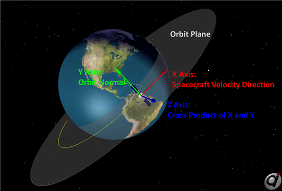
VNB
Description:
•X-axis: Vector pointing in the direction of the Spacecraft's velocity •Y-axis: Vector pointing in the direction normal to the orbit •Z-axis: Vector perpendicular to the x- and y-axes, forming a right-handed coordinate system •Origin: Center of the Spacecraft |
Prior to setting the Spacecraft's attitude state, its attitude reference frame must be set:
Spacecraft1.AttitudeRefFrame = "VNB";
// or
Spacecraft1.SetAttitudeRefFrame(3); |
The EulerAngles property can be used to display the Euler Angles that define the orientation of the Spacecraft BCS with respect to its current attitude reference frame:
Report Spacecraft1.EulerAngles; |
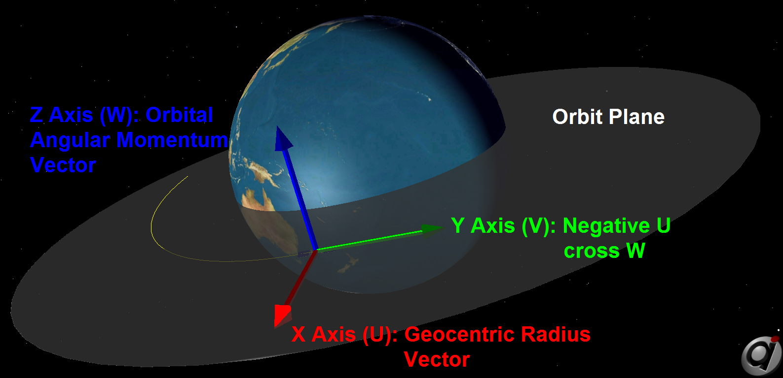
UVW
Description:
•Z-axis: Vector pointing in the direction normal to the orbit (along the angular momentum vector) •X-axis: Vector pointing in the direction of the Spacecraft's position vector •Y-axis: Vector perpendicular to the x- and z-axes, forming a right-handed coordinate system •Origin: Center of the Spacecraft |
Notes:
•The UVW coordinate system is quasi-inertial, in the sense that it is treated as an inertial coordinate system (for example, for the purpose of velocity conversions), but it is redefined at each point of interest. |
Prior to setting the Spacecraft's attitude state, its attitude reference frame must be set:
Spacecraft1.AttitudeRefFrame = "UVW";
// or
Spacecraft1.SetAttitudeRefFrame(4); |
The EulerAnglesUVW property can be used to display the Euler Angles that define the orientation of the Spacecraft BCS with respect to the UVW frame:
Report Spacecraft1.EulerAnglesUVW; |
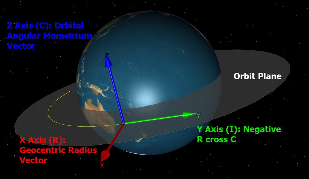
RIC
Description:
•Z-axis: Vector pointing in the direction normal to the orbit plane (along the angular momentum vector, also commonly called "cross-track") •X-axis: Vector pointing in the direction of the Spacecraft's position vector ("radial") •Y-axis: Vector perpendicular to the x- and z-axes, forming a right-handed coordinate system (also commonly called "in-track") •Origin: Center of the Spacecraft |
Notes:
•The RIC coordinate system is aligned with the UVW coordinate system, but is not considered quasi-inertial (it is not treated as an inertial coordinate system for the purposes of velocity vector conversions). |
Prior to setting the Spacecraft's attitude state, its attitude reference frame must be set:
Spacecraft1.AttitudeRefFrame = "RIC";
// or
Spacecraft1.SetAttitudeRefFrame(5); |
The EulerAnglesRIC property can be used to display the Euler Angles that define the orientation of the Spacecraft BCS with respect to the RIC frame:
Report Spacecraft1.EulerAnglesRIC; |
Relative Motion Frames
The following frames are Curvilinear reference frames, which are useful for relative motion analysis.
LVC (Cylindrical)
Description:
•X-axis: Relative along-track distance in the direction of θ •Y-axis: Relative cross-track distance Ζ in the direction normal to the leader Spacecraft's orbit plane •Z-axis: Relative radial distance projected in the leader Spacecraft orbital plane δρ •Origin: Center of the leader Spacecraft in the LVLH frame |
Notes:
•The LVC frame (Local-Vertical-Curvilinear) is aligned with the LVLH frame, therefore the positive direction of the (θ, Ζ, δρ) coordinates (shown in light blue) matches the direction of the LVLH vectors. |

LVC Coordinate System
The LVC coordinate system is shown in the image above, using the conventions defined in Adamo1. The basis vectors {Ô1, Ô2, Ô3} are shown centered on the primary Spacecraft and are aligned with the LVLH frame. The angle θ is the same as defined in the RIC Cylindrical frame and is measured in the orbital plane of the primary Spacecraft. The is measured form the orbital plane. The is the radial displacement difference between the primary and secondary Spacecraft's position magnitudes projected onto the primary Spacecraft's orbital plane.
The LVC coordinate system and RIC Cylindrical coordinate system are functionally equivalent, and only differ in the ordering of their basis vectors.
A Spacecraft's full state, position, or velocity can be converted to or from this frame using the RelativeMotionUtilities object.
RIC Cylindrical
Description:
•X-axis: Relative radial distance projection in the leader Spacecraft orbital plane δρ ("radial") •Y-axis: Relative along-track distance in the direction of θ (also commonly called "in-track") •Z-axis: Relative distance Ζ in the direction normal to the leader Spacecraft's orbit plane (also commonly called "cross-track") •Origin: Center of the leader Spacecraft |
Notes:
•The RIC Cylindrical frame is aligned with the RIC frame, therefore the positive direction of the (δρ, θ, Ζ) coordinates (shown in light blue) matches the direction of the RIC vectors. |

RIC Cylindrical Coordinate System
The RIC Cylindrical coordinate system is shown in the image above, using the conventions defined in Schaub and Junkins2. The curvilinear basis vectors {Ôr, Ôθ, Ôz} are shown centered on the primary Spacecraft and are aligned with the Cartesian RIC frame, hence the name "RIC Cylindrical". The angle θ is the same as defined in the RIC Spherical frame and is measured in the orbital plane of the primary Spacecraft. The is the same as the RIC cross-track distance measured from the primary Spacecraft's orbital plane to the secondary Spacecraft's orbital plane. However, is the in-plane radial difference between the secondary and primary Spacecraft's position magnitudes projected onto the primary Spacecraft's orbital plane.
The RIC Cylindrical coordinate system is similar to the RIC Spherical coordinate system. For the position of the secondary Spacecraft relative to the primary Spacecraft, the θ and ф angles are converted to arc lengths using the primary Spacecraft frame.
A Spacecraft's full state, position, or velocity can be converted to or from this frame using the RelativeMotionUtilities object. This frame can also be selected as the Coordinate Set used to propagate a HCW propagator.
RIC Spherical
Description:
•X-axis: Relative radial distance δr ("radial") •Y-axis: Relative along-track distance in the direction of θ (also commonly called "in-track") •Z-axis: Relative spherical distance ϕ in the direction normal to the leader Spacecraft's orbit plane (also commonly called "cross-track") •Origin: Center of the leader Spacecraft |
Notes:
•The RIC Spherical frame is aligned with the RIC frame, therefore the positive direction of the (δr, θ, ϕ) coordinates (shown in light blue) matches the direction of the RIC vectors. |

RIC Spherical Coordinate System
The RIC Spherical coordinate system is shown in the image above, using the conventions defined in Schaub and Junkins2. The curvilinear basis vectors {Ôr, Ôθ, Ôϕ} are shown centered on the primary Spacecraft and are aligned with the Cartesian RIC frame, hence the name "RIC Spherical". The angle θ is measured in the orbital plane of the primary Spacecraft and ф is measured from the primary Spacecraft orbital plane to the secondary Spacecraft position vector. The radial separation is the difference between the secondary Spacecraft and primary Spacecraft radii: = r2 - r1.
For the position of the secondary Spacecraft relative to the primary Spacecraft the θ and ф angles are converted to arc lengths using the primary Spacecraft frame. Therefore when moving from the primary Spacecraft to the secondary Spacecraft the θ and ф changes happen before the change.
A Spacecraft's full state, position, or velocity can be converted to or from this frame using the RelativeMotionUtilities object. This frame can also be selected as the Coordinate Set used to propagate a HCW propagator.
Custom CoordinateSystem Objects
Description:
•You can also reference your Spacecraft's attitude to a custom CoordinateSystem object •FreeFlyer will maintain the Spacecraft's attitude with respect to that CoordinateSystem as the Spacecraft is propagated or maneuvered, maintaining the attitude during each integration step •CoordinateSystems can be built using two Vectors as the axes, or by specifying a direction cosine matrix, Euler angles, quaternions, or the body coordinate system of a Spacecraft/CelestialObject/Star, or by chaining together multiple existing CoordinateSystems |
The screenshot below shows how to configure a Spacecraft to reference its attitude to a custom CoordinateSystem object through the Spacecraft object editor. The attitude can then be entered in any of the available attitude systems (Euler Angles, Quaternions, or Attitude Matrix).

Spacecraft configured to reference its attitude using Euler Angles with respect to a custom CoordinateSystem
In order to set the Spacecraft's attitude to use a custom CoordinateSystem in a FreeForm script editor, the attitude reference frame is set:
Spacecraft1.SetAttitudeRefFrame(CoordinateSystem1); |
The following properties can be used to display the Euler Angles, Quaternion, or Attitude Matrix that define the orientation of the Spacecraft BCS with respect to its Attitude Reference Frame:
Report Spacecraft1.EulerAngles, Spacecraft1.Quaternion, Spacecraft1.AttitudeMatrix; |
References:
1. D. Adamo, A Meaningful Relative Motion Coordinate System for Generic Use (AAS 05-306), Advances in the Astronautical Sciences, vol. 123, 2006.
2. H. Schaub and J. Junkins, Analytical Mechanics of Space Systems, Fourth Edition. AIAA, 2018.
See Also
•Attitude Systems Guide
•Orbit Reference Frames Guide
•Vectors and CoordinateSystems Guide
•AttitudeConvert Function
•RelativeMotionUtilities Properties and Methods